You are here:
Products List
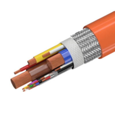
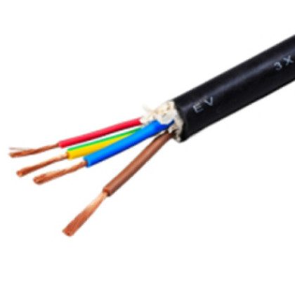
The electric vehicle charging cable is used to connect the electric vehicle charging device and charging infrastructure, thereby transmitting power to the electric vehicle. It is equipped with a certain number of signal lines, control lines, power auxiliary lines, etc. to ensure accurate control and safe operation of the entire charging process. Charging cables are generally used in charging stations, parking lots, hotels, residential areas, garages, and other areas. Portable charging cables can be placed inside the vehicle.

Cable Material :
|
Feature: |
|
|
Ambient temperature:-40℃~+70℃,-40℃~+90℃ |
Good EMI and EMC resistance to electromagnetic interference |
|
Rated voltage:AC 450/750V,DC 1000V |
Resistance to external pressure and thermal stress |
|
Halogeen free,follow the development-friendly products' developing direction |
Pass single vertical combustion test,high flame resistance |
|
Cold resistance,wear resistance,oil resistance,acid and alkali resistance,water resistance,UV resistance |
Pass single vertical combustion test,high flame resistance |
|
Product Advantage: |
|
High flexibility,minimum bending radius can be up to 5 ×OD (cable’s nominal diameter),easy to install and use; |
|
Excellent thermal stress:Pass GB/T 33594-2017 high temperature pressure test; |
|
Good oil resistance(mineral oil,fuel and gasoline resistance); |
|
Good environment resistance:Pass GB/T 33594-2017 artificial weather aging test; |
|
Excellent low temperature toughness:Pass the -40°Ccold bend test,cold impact test. |
AC Charging Cable:
|
Rated current |
Style of cable(mm²) |
Material Combination |
Insulation Thickness (mm) |
Sheath Thickness (mm) |
Reference Value of Cable Diameter (mm) |
Conductor Resistance at 20℃ (Ω/km) |
|
|
16A single phase |
3×2.5 |
TPE+TPE |
0.8 |
0.5 |
1.9 |
12.6-16.1 |
7.98 |
|
TPE+TPU |
0.8 |
0.5 |
1.1 |
11-14.2 |
26 |
||
|
XLPO+TPU |
0.7 |
0.5 |
1.1 |
10.6-13.7 |
|
||
|
XLPO+TPE |
0.7 |
0.5 |
1.8 |
12.0-15.4 |
|
||
|
16A three phase |
5×2.5 |
TPE+TPE |
0.8 |
0.5 |
2.1 |
14.9-19.0 |
7.98 |
|
TPE+TPU |
0.8 |
0.5 |
1.3 |
13.3-17.0 |
26 |
||
|
XLPO+TPU |
0.7 |
0.5 |
1.2 |
12.7-16.1 |
|
||
|
XLPO+TPE |
0.7 |
0.5 |
2 |
14.2-18.1 |
|
||
|
32A single phase |
3×6 |
TPE+TPE |
1 |
0.5 |
2.2 |
15.8-20.2 |
3.3 |
|
TPE+TPU |
1 |
0.5 |
1.3 |
14.1-18.0 |
26 |
||
|
XLPO+TPU |
0.7 |
0.5 |
1.2 |
12.9-16.4 |
|
||
|
XLPO+TPE |
0.7 |
0.5 |
2 |
14.4-18.4 |
|
||
|
32A three phase |
5×6 |
TPE+TPE |
1 |
0.5 |
2.5 |
19.3-24.5 |
3.3 |
|
TPE+TPU |
1 |
0.5 |
1.5 |
17.4-22.1 |
26 |
||
|
XLPO+TPU |
0.7 |
0.5 |
1.4 |
15.7-19.5 |
|
||
|
XLPO+TPE |
0.7 |
0.5 |
2.3 |
17.5-22.2 |
|
||
|
63A single phase |
3×16 |
TPE+TPE |
1 |
0.5 |
2.6 |
20.1-25.4 |
1.21 |
|
TPE+TPU |
1 |
0.5 |
1.6 |
18.1-23.0 |
26 |
||
|
XLPO+TPU |
0.7 |
0.5 |
1.5 |
17.0-21.6 |
|
||
|
XLPO+TPE |
0.7 |
0.5 |
2.5 |
18.9-24.0 |
|
||
|
63A three phase |
5×16 |
TPE+TPE |
1 |
0.5 |
3 |
25.0-31.7 |
1.21 |
|
TPE+TPU |
1 |
0.5 |
1.8 |
22.7-28.3 |
26 |
||
|
XLPO+TPU |
0.7 |
0.5 |
1.7 |
21.3-26.8 |
|
||
|
XLPO+TPE |
0.7 |
0.5 |
2.9 |
23.4-28.6 |
|
DC Charging Cable:
Rated current
Style of the cable
Material Combination
Insulation
Sheath
Reference Value
Conductor
80A
3×25+2×4+2P×0.75
TPE+TPE
1.2 1.0 0.5
3
24.5-31.0
0.78
TPE+TPU
1.2 1.0 0.5
1.8
22.2-28.1
0.78
XLPO+TPU
0.9 0.7 0.5
1.7
20.7-26.3
4.95
XLPO+TPE
0.9 0.7 0.5
2.8
22.8-28.9
26
125A
2×35+1×25+2×4+2P×0.75
TPE+TPE
1.2 1.2 1.0 0.5
3.3
27.7-35.0
0.554
TPE+TPU
1.2 1.2 1.0 0.5
2
25.2-31.9
0.78
XLPO+TPU
0.9 0.9 0.7 0.5
1.9
23.8-30.1
4.95
XLPO+TPE
0.9 0.9 0.7 0.5
3.1
26.1-33.0
26
200A
2×50+1×25+2×4+2P×0.75
TPE+TPE
1.4 1.2 1.0 0.5
3.7
32.4-40.9
0.386
TPE+TPU
1.4 1.2 1.0 0.5
2.2
29.6-37.3
0.78
XLPO+TPU
1.0 0.9 0.7 0.5
2.2
27.9-35.3
4.95
XLPO+TPE
1.0 0.9 0.7 0.5
3.6
30.6-38.6
26
250A
2×70+1×25+2×4+2P×0.75
TPE+TPE
1.4 1.2 1.0 0.5
4.2
37.1-46.8
0.272
TPE+TPU
1.4 1.2 1.0 0.5
2.5
33.9-42.7
0.78
XLPO+TPU
1.1 0.9 0.7 0.5
2.4
32.4-40.9
4.95
XLPO+TPE
1.1 0.9 0.7 0.5
4
35.5-44.8
26
(mm²)
(Insulation+Sheath)
Nominal
Thickness(mm)
Nominal
Thickness
(mm)
of Cable Diameter
(mm)
Resistance
at 20℃(Ω/km)